Need Help?

For students managing design work, sketching, deadlines, and creative pressure — and for educators seeking greater clarity in their teaching — this blog offers focused, practical support in Design & Technology, from visual communication and design process thinking to digital fabrication. For those seeking more tailored support, I am also available for student consultations and teacher workshops. Since 2007, DesignJournalSOS has helped readers navigate real classroom challenges with grounded strategies and insight. Have a question or topic you’d like explored? Your reflections are welcome — they help keep this space alive and growing. Copyright © 2007–2026 Daniel Lim
Showing posts with label Product Design. Show all posts

28 September 2026

Free Sennheiser XS Lav Microphone Clip STL: Flat Base & Snap-Fit Design

Want to 3D-print a holder for your Sennheiser XS Lav microphone? The flat-base STL is FREE. Download the free flat-base microphone clip on Gumroad for personal or classroom use, then add your own adhesive hook-and-loop fastener to mount it where you need it. The phone-overhang option shown below is available in a separate paid bundle.

This small clip also makes a useful design lesson you can hold in your hand. For my Sennheiser XS Lav USB-C microphone, two measurements shaped the fit: a 6.5 mm gripping diameter and 5 mm of available gripping length. The detail that keeps it in place is where the cradle ends.

3D Rendered photograph: An overhang printed bases for an iPhone with case.
Orange Sennheiser XS Lav microphone clips: phone-overhang V4 and flat-base V3 side by side
Physical photograph: two printed bases for different mounting preferences.

Why the snap-fit clip must pass the midpoint

Matching the diameter gives the microphone somewhere to sit. Retaining it needs another detail: the sides of the cradle must extend above the circle’s horizontal centreline.

A semicircular cradle ending at that line leaves an open path upwards. It can support the capsule, but provides no geometric snap retention. Extending the lips beyond the midpoint makes the entrance narrower than the diameter being held. The lips flex apart during insertion, then recover around the capsule to resist it lifting out. That is the basis of the “click-in” action; an audible click is not guaranteed.

I used a nominal 6.7 mm cradle bore around the 6.5 mm gripping diameter and a 240° wrap. The 5 mm gripping length keeps the cradle within the available cylindrical section. Diameter, opening, wall thickness and material flexibility work together to determine the fit.

Flat V3 microphone clip CAD dimensions showing the 6.7 mm bore, 5 mm cradle length and 240 degree wrap
CAD drawing: the cradle wraps beyond the centreline to form a retaining opening. Click to enlarge.

This follows the same habit I discussed in sizing a design around an accessory: start with the object that must fit, then build the surrounding form. The steel rule positioning block provides another example of a small retaining detail changing how parts meet.

Flat base or phone-overhang mount?

The free flat-base version is a straightforward starting point if you prefer choosing your own mounting position. It offers a 15 × 10 mm mounting surface for users who prefer adhesive hook-and-loop fastening, such as Velcro. The fastener is supplied separately; its thickness and adhesion need to suit the chosen surface.

Sennheiser XS Lav microphone with furry windscreen seated in the orange flat-base clip
Physical photograph: the flat-base clip with the microphone seated.

The overhang version is my preference. It clips over the phone edge and adds rounded internal gripping ribs for extra hold. This version was designed around my 11 mm phone-and-case thickness. A different case can change the contact, flexibility and grip, so measure yours before printing.

Sennheiser XS Lav microphone seated in the orange overhang phone clip
Physical photograph: the overhang base and microphone cradle.
Overhang V4 CAD drawing showing the phone channel and rounded internal gripping ribs
CAD drawing: rounded ribs narrow the phone channel to provide the intended grip. Click to enlarge.

Both versions have been printed, and the photographs show the microphone seated. Check the fit gently on your own print, keep the acoustic opening and phone controls clear, and inspect for cracking or looseness. Print material and tolerances still matter.

Get the free flat-base STL—or choose the phone mount

To try the design, choose Flat Base V3 — Free on Gumroad and enter US$0; a tip is optional. The download includes the STL, a print-and-fit guide and a personal/classroom licence. If you prefer the phone-edge mounting option, the US$3.99 bundle includes both the overhang and flat-base STLs.

Want to sell physical prints? Choose the corresponding commercial option: US$11 for the flat base or US$14.99 for both designs. Each allows up to 100 physical clips in total; the bundle shares that allowance across both designs. Designer credit is appreciated but optional. Digital files may not be resold or shared under either licence.

Get the FREE flat-base microphone clip STL on Gumroad

For design students, the lesson is practical: do not simply record a critical dimension. Explain what it controls. Here, a diameter establishes the seat, a length defines the available contact, and the lips above the midpoint create the retaining geometry.

#SennheiserXSLav #MicrophoneClip #SnapFitDesign #CriticalDimensions #3DPrinting #DesignAndTechnology #DesignJournalSOS

Like my contents? Support me, support my work? Buy me a Coffee? 

25 September 2026

3D-Printed Steel Ruler Positioning Block: 45°/90° Marking & Critical Dimensions

A marking tool can look finished long before it works as intended. With a steel rule positioning block, the question is not only whether the body presents 45° and 90° edges. It is also whether the rule sits where you expect when you bring the tool to a piece of wood.

That small question shaped Version 4 of my 3D-printed positioning block.

Physical photograph of the printed V4 steel rule positioning block with a steel rule inserted.
Physical photograph: the printed V4 block with a steel rule inserted.

Combining two useful functions

I began with a compact block that offered two common reference angles. The 90° face helps when a line must cross a board squarely; the 45° face offers another familiar layout direction. This is an example of the Combine step in SCAMPER: putting related functions into one tool, then checking whether they still work well together. It is the same question I explored when combining functions in another printed design.

The steel rule is the working edge, so the printed body needs to position it reliably. A printed thumb screw pushes from one side. The exterior reference faces then meet the edge of the workpiece while the ruler remains available for marking.

Physical photograph of the V4 block body and matching printed thumb screw.

Physical photograph: the body and matching printed screw.

A small dimension changes the contact

In Version 3, the rule rested on a seat against a straight shoulder, with the screw contacting its opposite edge. The CAD section below makes that arrangement visible. It established the basic relationship, but it also drew attention to the rule's upper edge: a flat shoulder does not place a lip above it.

V3 CAD section showing the ruler resting against a flat shoulder and contacted by the screw.
V3 CAD section: screw, ruler and flat shoulder before the retaining change.

Version 4 adds a 2 mm-high, 2 mm-deep undercut with a 45° internal face along that shoulder. The rule tucks beneath the lip; the existing screw has enough extra travel to press it toward the sloping face. The screw trough was extended by 2 mm to make room for this movement. This is a digital design result, not a claim of measured holding force.

The number that matters first is the thickness of the actual steel rule. The CAD checks considered rules from 0.3 to 1.0 mm thick. Within that range, the geometry gives 1.7 to 1.0 mm of insertion beneath the lip. The 2 mm dimension describes the retaining recess, not a typical rule thickness. This follows the same principle as modelling the accessory before sizing the product around it.

V4 CAD section showing 0.3 and 1.0 mm rule thicknesses beneath the 2 mm-high 45° retaining lip.
V4 CAD section: the 45° lip and its relationship to two ruler thicknesses.
Physical photograph of the printed V4 block profile with the steel rule seat visible.
Physical photograph: the printed profile. The photograph does not measure grip strength.

Function and finish belong together

The body remains about 80 × 55 × 18 mm, with a 45° diagonal reference face, a 90° face and a round finger opening. The softened outside corners and edges carried forward from Version 3 make the form look more resolved and feel less abrupt. I kept the functional junction at the rule seat crisp, because rounding that point would change the contact with a thin rule. In a design drawing, form, function and critical dimensions should support one another rather than be treated as separate concerns.

V4 CAD drawing of the 80 by 55 mm body and 45° and 90° reference faces.
V4 CAD drawing: body envelope and the two workpiece-contact faces.
Physical photograph of the positioning block and rule placed at a workpiece edge.
Physical photograph: one reference-face orientation at a workpiece edge.
Physical photograph of the block and rule held in an alternative orientation at a workpiece edge.
Physical photograph: an alternative layout orientation.

The V4 download includes the body, matched thumb screw and a thread-fit coupon. The printed thread is a custom pair, so I would check the coupon first, inspect the retaining lip in the slicer, then test the assembled tool with the particular rule and workpiece before making a project mark. The supplied photographs show a printed example; they do not establish marking accuracy or long-term retention.

Download the Steel Rule Positioning Block V4 files on Gumroad.

Small details such as the rule's thickness, a two-millimetre recess and a carefully kept sharp contact edge decide whether combining useful features becomes a useful tool.

#SteelRule #MarkingGauge #SCAMPER #CriticalDimensions #3DPrinting #Woodworking #DesignAndTechnology #DesignJournalSOS

Like my contents? Support me, support my work? Buy me a Coffee?

23 September 2026

3D-Printed Sandpaper Holders: Flat & Rounded Sanding Blocks for Small Projects

Small pieces are often the most awkward to sand. A loose strip of sandpaper may seem convenient, but it can fold, slip or simply follow the movement of the fingers. This makes it harder to keep a surface flat, produce a consistent chamfer or follow a controlled curve.

I originally designed a compact flat sandpaper holder to give a 30 mm abrasive strip a firm, predictable backing. I have now added a second holder with a long, gradual convex face. The fastening idea is shared, but the two tools serve different purposes.

Flat and rounded white-and-orange 3D-printed sandpaper holders displayed together on a dark surface.

Photograph: the flat and rounded holders show how changing the backing shape changes the sanding task.

One fastening idea, two sanding surfaces

Both holders use a removable rear clamp and a large printed thumb screw. The abrasive strip passes over the working face and is held at the rear. When it wears out, the screw can be loosened and the strip replaced.

The important design decision is the form beneath the abrasive. Sandpaper alone is flexible; the holder controls how that flexibility is used.

The flat holder: keeping flat work flat

The original holder has a rigid flat backing and an 80 x 30 mm footprint. It is useful for small flat faces, controlled chamfers and edge refinement where the intention is to preserve a straight or planar surface.

With loose sandpaper, fingertip pressure tends to concentrate in small areas. The paper can also curl around an edge and round it unintentionally. A flat holder spreads pressure over a defined face and gives the hand a more stable reference.

Compact white and orange flat sandpaper holder with abrasive paper secured beneath its clamp.

Photograph: the original flat holder assembled with a 30 mm abrasive strip.

For chamfering, hold the work securely, mark a guide line and maintain a steady angle. Light, counted strokes make matching edges easier to compare. The tool improves control, but the accuracy still depends on the user's judgement.

The rounded holder: following gradual inside curves

The second holder replaces the flat working face with a long convex profile. It is intended for broad concave surfaces, shallow inside curves and gradual transitions that a flat block cannot follow. Its narrow nose can approach tighter areas, while the wider part of the curve provides a larger sanding surface.

Side view of a white 3D-printed rounded sandpaper holder with a long convex upper face.

Photograph: the side profile reveals the gradual convex face and narrow nose of the rounded holder.

This is a useful lesson in matching a tool to the geometry of the intended result. A flat block helps preserve flatness. A curved form supports the abrasive while allowing it to contact a concave workpiece more evenly. Neither shape is universally better; each is selected for a different outcome.

Assembled white-and-orange rounded sandpaper holder viewed from the rear with a large printed thumb screw.

Photograph: the assembled rounded holder, rear cap and hand-tightened printed screw.

A shared clamping system

The rounded holder uses the same custom printed screw interface as the flat design. Its main body, rear cap and thumb screw are separate parts, making the clamping action visible and easy to understand.

Three separate printed parts of the rounded sandpaper holder arranged on a dark surface.

Photograph: the rounded body, removable rear cap and matching thumb screw separated for assembly.

Both holders accept 30 mm-wide strips. About 175 mm is a sensible starting length; fit the strip, confirm its path and then trim if required. Tighten the screw by hand only. The thread is a matched printed pair and is not intended for a standard metal M10 fastener.

Flat and rounded 3D-printed sandpaper holders shown together for direct size and form comparison.

Photograph: comparing the compact flat holder with the longer rounded profile.

Printing considerations

The flat holder is supplied in support-free STL orientations and includes a thread-fit coupon. Printing the coupon and screw first allows the thread fit to be checked before the complete tool is made.

The rounded body needs selective removable support beneath the rear retaining rails. The cap and screw print without support. A prepared Bambu Lab P1S 3MF is included with the download. Its slicer estimate is approximately 1 hour 58 minutes and 40.25 g of filament, including purge and support; actual results will vary with printer, material and settings.

Dimensioned CAD drawing of the rounded sandpaper holder.

CAD view: the rounded holder body and cap measure 80 x 30 x 30 mm, with an 88 mm overall length including the screw.

Slicer path graphic showing the printed thread and removable rear support of the rounded holder.

Slicer evidence: selective support is confined to the rear retaining rails.

The flat holder has been physically printed, assembled and function-tested in PLA on a Bambu Lab P1S with a 0.4 mm nozzle. The supplied photographs confirm that the rounded holder has also been printed and assembled, and its 3MF has passed slicer checks. Its sanding performance, paper retention, support-removal quality and durability still need further physical evaluation.

Sand effectively and safely

Start with a grit suited to the amount of material that must be removed, then move progressively to finer grits. Test the chosen holder on scrap before working on the project. Secure small workpieces, wear appropriate eye and dust protection and stop using any printed part that cracks or allows the abrasive to slip. PLA can soften in high heat, so do not leave the tool in a hot vehicle or near heat-producing machinery.

The files are available separately for each holder, or together as a discounted set:

Download the Flat or Rounded 3D-Printable Sandpaper Holder on Gumroad

A simple holder does not replace skill. It gives the hand a backing shape that makes the intended result easier to judge and repeat. The flat and rounded versions show how one small change in form can produce two distinct workshop tools.

#3DPrintedSandpaperHolder #HandSanding #WoodworkingTools #3DPrinting #WorkshopSkills #MakerEducation #DesignAndTechnology #DesignJournalSOS

Like my contents? Support me, support my work? Buy me a Coffee?

02 December 2025

Wooden Metatron Standing Clock - Adobe Illustrator and Laser Cut

Availability of technologies like the laser cutting machine with illustration softwares (the Adobe Illustrator) has made design and prototyping the Archangel Metatron Standing Clock an easy affair.


The Archangel Metatron Standing Clock was almost designed rom scratch. I got the Metatron sacred geometry online and had it vectorised. 

I held the naked clock mechanism on one hand, and visually determined a nice mounting height with a steel rule from the table top. The spine, was designed as I measured (and noted) the dimensions of the clock mechanisms case. There, was where I figured out details of holding, securing, and how it may stand on two layers of a rounded base. Decisions about the final dimensions are scribbled on scrap paper (below left).


So what inspired the act to design, and make? Firstly my living room is missing a clock. Secondly I wanted to see how quickly I can create one. Thirdly, a Metatron geometry reminds of balance and harmony in the universe. 

#metatron #archanglemetatron #clock #clockdesign #standingclock #designandtecnology #productdesign #lasercutting #adobeillustrator #innovation #creativity #time

Support me, support my work? Buy me a Coffee? https://www.buymeacoffee.com/mrdanielsos

22 June 2025

Dog Note and Pencil Holder – From Sketch to 3D Print with Tinkercad


Every students’ first idea about what they want to design and make. 

But how can pencil holders be out of the ordinary, not the usual box and slot type?

Ideas Generation


First steps to ideas generation is always the exploration stage. 

Nothing fanciful at this stage. I’m just exploring how to hold a piece of papers starting with a simple block. It’s not a time to think about shapes and forms now unless the challenge is ‘form before function’, which is not the case now.

Using block as a starter helps me focus better on the function - about how to make things work. About how to make holding a piece of papers effective, easy, and maybe fun.

Ideas about using curved slots to hold paper is not new in my experience. I’ve explored ways to hold notes quite extensively 10 years back. I will not be repeating them here but you can find various posts related to note holders here. 

But I’ll give you a quick summary about the curved slot concept. 

Paper tends to want to stay flat when you bend it. 


That’s the elasticity in the structure of paper. Making use of this principle, I figured out if I have a narrow curved slot compared with a straight one, the paper can be held in place as it tries to straighten out but couldn’t. It’ll remain ‘stuck’. On the other hand, it’ll slide out easily if it’s a straight slot.

Exploring more Ideas into the Refinement and Development Phase

In this series of sketches I’ve ventured into shapes and forms. Borrowed from the profile of a dog and the idea that the dog is bringing the owner ‘newspapers’ from the door, this is the familiar “Meaningful Design” design teaching approach back in 2009 where I presented in the MOE Design & Technology Conference 2009 to share the concept of bringing ‘meaning’ into ‘designs’ - where design tells a story. You can find the post here.

Before this students’ work in D&T had been craft like, mainly functional ornamental works which I find lacking thoughts, emotions, and any fun at all.

The Final Concept Ready for Rapid Prototyping


I drafted the final concept in various perspectives while working out if the idea would work in real life. By this time I’ve already gotten the critical dimensions of a typical pencil. Worked out a rough form and proportion of the design. 

I’ve always emphasised with my students it is very important to include the items to be held when presenting their ideas. Most students would draw a holder, but without the items they are intended to hold. This way of designing has several problems:
  1. You cannot gauge if the holder will be the right size without the items drawn in, proportionately.
  2. You cannot tell if the product would work because there is no context to the holder. It is holding nothing.
  3. You will always have the illusion that it will work.


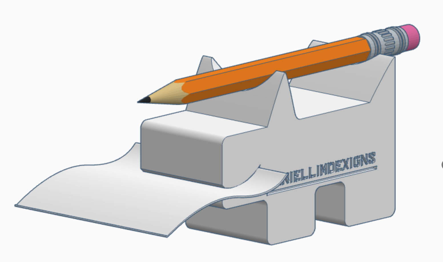
To build the form of the dog, building it one block at a time will take too long. Making slots at the mouth will involve multiple steps that require many steps with negative cuts. With the ‘Sketch’ tool, the profile of the dog can be sketched out easily.

The image on the left shows shadows (translucent orange) of ‘hole’ shapes used to cut the other slots in the design.

Tinkercad Model Breakdown


Above Left: Here you can see the 3D model of the dog profile and its respective ‘hole’ shapes for the pencil and paper slots.

Above Right: That is another variation using the same dog profile from the left. In this design I cut a circular top for a pencil to rest on, instead of putting it through a vertical slot.

In this example I’ve shown that once you have a base design, you can then copy and modify it later into other variation. This step is useful if you want to test different design configurations or to find out which works best.

Contextual Presentation
 

A quick model mock up of how the holder may look like with its respective items. I found the pencil from the search function. And I used the sketch function to draw the paper.


Two variations of the Doggy Note & Pencil Holder

Conclusions

The moment of truth - if the idea or concept works or not - is in the 3D print out. 

I made a couple of iterations to the gap of the mouth to make the paper ‘stick’ better and not slide out too easily. A curved gap of about 1mm is good but printing the holder vertically posed challenges to the horizontally orientated mouth. The top curve will need to be supported. I chose the ‘tree’ support from the print bed. 

The larger curved slot at the back are for additional papers, and that too cannot be too wide. If the gap is too wide the stack of papers will feel loose on the holder. Mine is about 4mm wide at the back. Trying to store a few pieces of papers on any gaps more than 4mm wide, even if it is curved, will feel weak as far as grip is concerned.

Overall, the prints turned out quite well. What I need to work on next are 3D printing settings to optimise print time and print quality.

I hope you like this post. Let me know what you think. Or share with me what you would like to see in my future posts.

#3Dprint #tinkercad #productdesign #pencilholder #noteholder #innovation

Like my contents? Support me, support my work? Buy me a Coffee? https://www.buymeacoffee.com/mrdanielsos

20 June 2025

Design a Snail Cup Coaster with Tinkercad with the "Sketch" Tool

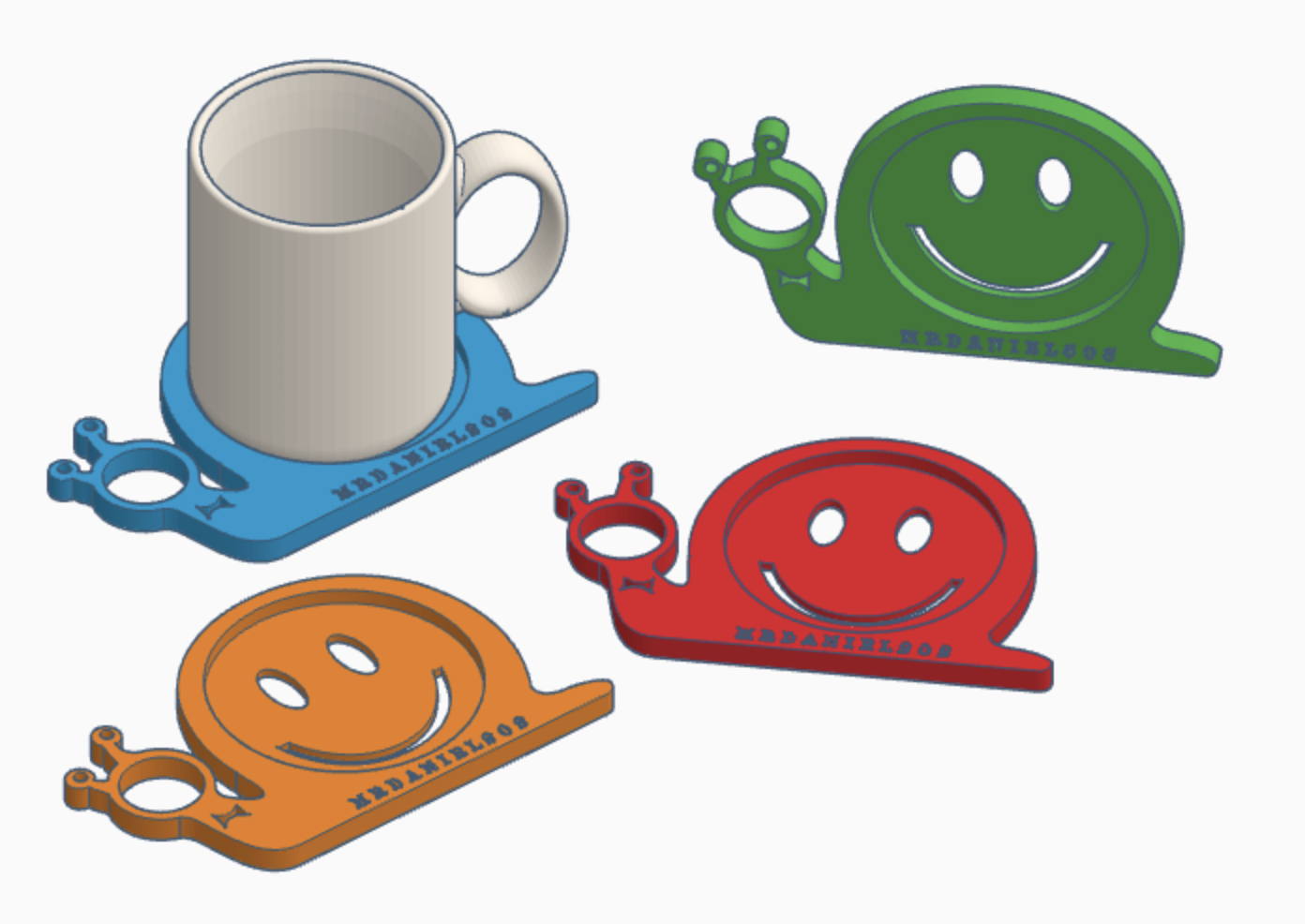
SNAILS Coaster Design on Tinkercad

The thought about making a snail coaster is not new. About a decade or more ago I designed a snail coaster and had it cut out with a laser cutter. Which was used a a door gift to all the participants in a Design & Technology teachers conference. 

SNAILS again

Here again I thought of snails when I begin tinkering with Tinkercad. Some things never change.

Don't they look so cute when you have a family of them?


TOP VIEW

45 Degrees View


How Do I Make This Profile in TInkercad? 

I am guessing you want to know how I made this. If you used Tinkercad you'll quickly understand that this snail profile will be extremely tricky if you use the basic combining shapes method. Not only that - you may go crazy.


Glad that I found the "Sketch" tool. This tool is an incredible feature. I cannot NOT use it as soon as I learned about what it is and what it can do in Tinkercad. While it's features with the pen tool cannot be compared with the likes in Adobe Illustrator - however once it's limitation & simplicity is understood - more complex shapes can easily be created.

Several layers of "sketch" took place to create the final snail coaster profile I was looking for. 

Something that was impossible for me in Tinkercad is now possibilities only limited by my imagination. 

------------

Want to learn Tinkercad and start designing? Feel free to contact me at mrdanielsos@yahoo.com.sg for more details.

Like my contents? Support me, support my work? Buy me a Coffee? https://www.buymeacoffee.com/mrdanielsos
 

How to Design & Print a Clipboard & Pencil Holder with Tinkercad

What do you do with a clipboard?

You write.

What do you write with? A pen or a pencil.

Since I often draft my work with a pencil, I thought—why not make my own clipboard pencil holder?


Modelling the Idea

In the example above, you’ll see how I like to model my designs. I copy and paste each iteration as I go, partly to document the process and partly to save time—if I need an edit, a spare part or want to revisit an earlier design, it’s just a copy-paste.

It also makes for a clean presentation. You can easily follow the steps of the clipboard pencil development.


Functional Iteration: Add a Grip Gap

One of the key refinements was adding a gap to improve the pencil’s grip. Unfortunately the PLA filament does not have the elasticity to flex. And so I ended up with a full ring design.

Put to Other Use?

Interestingly, I  also played around with placing it in different locations—on the side of the table, for example—where it worked surprisingly well.


Let's get that thing to work. The Hexagon Problem

Here’s where things got tricky.

The pencil slots were intentionally designed as hexagonal meant to match the cross-section of a typical pencil. I accounted for the exact dimensions of the pencil in my 3D model—but forgot about tolerance.

The 3D printer has a 0.4mm nozzle. That means it will print 0.2mm both sides of the printer head. As a result, the pencil didn’t fit, the hole was too small. After widening the hole by 0.4mm and more, it fit but was still a little loose. 

If I were to redesign the slot, I’ll make it round.


This clipboard pencil holder works just as expected. It fitted perfectly with the double clip. It’s magical when the pencil seem to float behind the spine of the double clip. Taking the pencil out and putting it back is a breeze. Overall I quite like the outcome. 


Above: Close-ups of the back view

Lesson Learned: Prototype the Pencil Slots First

Here’s a key insight from the process:

Next time, I’ll isolate and print just the part that holds the pencil—and do it in a range of slightly different profiles (round, hexagon, and so on) and sizes. That way, I will be able to test all the options at once and pick the best fit before embedding it into the full design. This will save filament, time, and frustration.


Your Turn

I hope you enjoyed this creation.

If it sparked your curiosity, why not try designing your own clipboard pencil holder? It doesn’t have to be based on mine—but feel free to borrow the idea and evolve it into something that fits your way of working.

And if you do, I’d love to see what you come up with. Share your designs with me! 

------------

Want to learn Tinkercad and start designing? Feel free to contact me at mrdanielsos@yahoo.com.sg for more details.

Like my contents? Support me, support my work? Buy me a Coffee? https://www.buymeacoffee.com/mrdanielsos