Need Help?

For students managing design work, sketching, deadlines, and creative pressure — and for educators seeking greater clarity in their teaching — this blog offers focused, practical support in Design & Technology, from visual communication and design process thinking to digital fabrication. For those seeking more tailored support, I am also available for student consultations and teacher workshops. Since 2007, DesignJournalSOS has helped readers navigate real classroom challenges with grounded strategies and insight. Have a question or topic you’d like explored? Your reflections are welcome — they help keep this space alive and growing. Copyright © 2007–2026 Daniel Lim

07 July 2017

Beefing up Student's Work - Tackling Common Mistakes

Below are samples of my students works at the development stage. 'Beefing' up is done on my iPad Pro after a photo is taken off the relevant pages. Some 'beefing' up is prepared before the lesson, some done live in class. Student's original A3 works on paper are untouched.

Summary of examples:
Student's work (1):
Lots of a variety of sketches but not catogorised with suitable sub-titles. Making understanding difficult. Beefing up on development sketches focusing on selected features from a solution.
 
Student's work (2):
Student sketched parts with changes from one to the other without referencing to the solution. Making page look like a catalogue of parts. Beefing up includes sketching in pens/pencils on the improved features.
 
Student's work (3):
Student had difficulty sketching in pens/pencils inclined at an angle on an isometric block. Beefing up includes suggestions to overcome (temporarily) lacking in skills to sketch using a 2-dimesional approach.
 
Student's work (4):
Student sketched in 2D and thinks the process of development is complete. However sketches in 2D fail to show how a product/object is like in real world 3D form. Beefing up includes two ways to represent a 2D shape three dimensions - a flat organic shape or a spherical organic shape. (using contour lines to represent surface curvature).
 
Student's work (5):
Student's work shows a variety of modifications to the size of a part of the solution. However all of the sketches did not show what it is suppose to hold. Beefing up includes showing items that is being held and what other additional supplementary sketches can pop up after including items.
 
Student's work (6):
This example is one of the most common mistake students make. Almost every student make the mistake of drawing the items to be held / stored on the holder too tiny. It can be very comical when the product is drawn in real size while keeping the proportions of the size of the pen/pencils held in there. Beefing up includes sketches of pens/pencils appropriately sized for the proposed holder.


Student's work (1)
Student submitted this page of development (on shapes).
At a glance one could not quickly tell the differences for each of the variations made in the page.

A suggestion to categorise specific focus for modifications.
Tips: Highlight intent with quick notes to inform reader (marker) what is being done.

I extracted a section of the student's work for a live demonstration on how presentation of sketches could be made more obvious. Focusing on variations for the 'legs' of the product I exaggerating the sizes to show 'changes' and how those changes affects the looks of the original solution. 
Important: At the end of the exercise a decision must be made to select the best combination.


Another demonstration showing various options for the body.
And how changes can affect the other parts of the solution.

Student's work (2)
When I saw this I thought I saw a catalogue of hardware parts.
Picking parts of a product and drawing variations out of them in silo does not help in design development. There is not way to visually assess how the overall product will look like when fitted with each of those variations.

Suggestion to draw parts with the body remaining constant. i.e. no change in shape or size. Only varying size of 'wing' and how it can subsequently affect the way it hold pens/pencils.

Student's work (3)
Student came to me with difficulty sketching in pens/pencils at an angle on a 3D block.

My suggestions: Student can sketch them in later (or after teacher's intervention). However at that 'stuck' moment, one way to get out is to draw the same solution on its 'Side View'. It is clear that once it is sketched on its side view, drawing pens / pencils at an angle becomes more manageable. With some help and more demonstration the student should be able to draw pens/pencils into the 3D block.

Student's work (4)
This example shows how a sketch can be taken further. Many students end up with a 2D sketch and expect that it is sufficient for development. The problem with a 2D sketch is that it does not show if this solution is a flat (block) or a spherical organic form.

A solution must eventually be presented with its third dimension be it using the isometric, perspective, or oblique method or in orthographic forms. Unless product is a printed image on paper.

Here I demonstrated very quickly how this 2D whale shape can either be a flat Isometric or a spherical organic form. 
Tips: Drawing contour lines on a spherical organic form is critical in showing curvature.
 
Student's work (5)
 
This student followed the instruction to draw variations of the parts (in this example the wings). However he has forgotten to include what the wings are for? That is to hold pens/pencils. But they are no where to be found. Therefore making proposed sketches meaningless.
 
Bottom right shows teacher's intervention to show how pens/pencils could be added and how the shapes and sizes of the wings  may affect the total number of pens/pencils and/or the way they are being slotted in.

Student's work (6)
Every time when I see students draw like this, I like to show them how HUGE their proposed design is relative to the objects they are holding. Usually my students will go 'WOW! I didn't know I drew them so BIG?"

On the right of the page is how BIG the product will be like. At the bottom right is an example how big the pens/pencils' should be drawn instead. You must have a good sense of proportion between the holder and what will be held/stored in it.
 
-----------------------------------------------------------------------------------------
If my posts helped you in one way or another, I would like to hear from you.
If you have feedbacks or suggestions or differing in views I would like to hear from you too.

30 June 2017

Pictorial Idea Generation and Development

This post is an extension and a supplement to "Coursework Experiential Journal Component 2016 Example" that was originally created as a guide and reference material for my Secondary 3NA student mini coursework. I will not repeat information I have already posted previously.

What you'll see in this post are pictorial/visual examples on Development (and refinements) in a design journal. The examples do not represent any complete section of a journal. They serve as a starting point - an example - a demonstration - a suggestion - a recommendation - etc. to show what sort of contents may go into, say development, and how you can present your research and information in the journal. 
 
Use them as a reference and a guide to start or to improve your journal. Make informed choices on your own on what your takeaways should be after looking at the materials in here. Do not copy. 
 

If you find this helpful, I would love to hear from you. If you have suggestions, please do not hesitate to link up with me.
 
Topics you'll find below:
1) Ideas Generation (SAMPLES) using Existing Products as Starter/Inspirations [Updated 39 June 2017]
2) Selecting (SAMPLES) Best Idea for Development (using Decision Matrix) [Updated 39 June 2017]
3) DEVELOPMENT [SHAPE AND FORM] [Updated 39 June 2017]
4) DEVELOPMENT (SHAPE & FORM and FUNCTIONALITY [Updated 27 July 2017]
5) DEVELOPMENT (Determine SIZES with CRITICAL DIMENSIONS) [Updated 28 July 2017]
6) DEVELOPMENT (Determine SIZES with ANTROPOMETRIC DATA) [updated 28 July 2017]
 
Ideas Generation (SAMPLES) using Existing Products as Starter/Inspirations
(email me for more details to learn about using Existing Products as Starter/Inspirations for Ideas Generation)
 

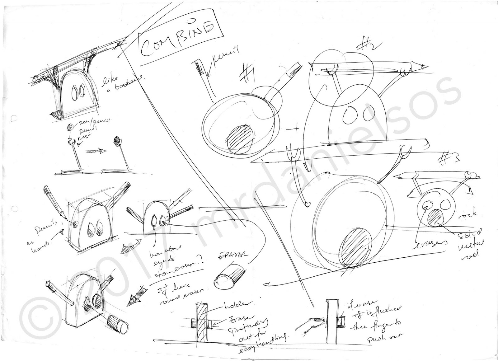
First two images shows ideas generation using existing products as initial source of inspirations. Existing products used have nothing to do with stationary holders.

Image above shows ideas combined to create a new hybrid. This is one of the outcomes you want to have when generating ideas. Combining ideas can give you unexpected interesting solutions.
 
Selecting (SAMPLES) Best Idea for Development
(using Decision Matrix)
(email me for more details to learn about using the above)
 
 
The Decision Matrix is one of the most convenient way to select a best idea from a few good ones. Here I selected five ideas for consideration where one of them will be selected for development. I set a few criterion what makes up the attributes for considering the best idea. Then use weightage and ratings for each idea for computation.
 
 
The above example shows Idea 4 scoring the highest.
Idea 4 will be redrawn for development. See below.


Development (SAMPLES) using Attribute Listing / Morphological Method
 
DEVELOPMENT [SHAPE AND FORM]
 
(email me for more details to learn about using the above)


Attribute Listing or Morphological Analysis (and also SCAMPER) are not just Ideation tools. They can also be used for refinement purposes.
 
Individual parts / features are selected one at a time to make changes one change at a time. E.g. I pick the body to make changes to shapes and forms. Then I refer to the Morphological table and looked under, say 'Shape', that could be circle, square or a triangle, etc. I proceed to change the body cross-section to the various shapes - just to see how my original selected idea might look like with different cross-sectional shapes. At this moment I would also need to consider the overall functionality as while you change anything, in this case the cross-sectional shape, the change will affect the way it works (or how it will be holding/storing the pens or pencils) or how the 'legs' should be installed, etc.
 
When developing a product's shape and form you MUST always keep in mind the idea of working towards finalising (e.g. the shape, size, dimensions, colors, jointing methods, etc) a solution in mind. This is NOT like in the exploratory mode when you were generating ideas earlier on.

Above is an example of my student's chosen idea for development. I made use of the attributes for each part of the object (in this case the difference parts of the fish) and made a couple more refinements on its shape and form. NOTE: What is not shown in the above example are placement pens and pencils within each possible variety of shapes. You should put them in.
 
DEVELOPMENT (SHAPE & FORM and FUNCTIONALITY)
 
Shown on the right is a sample of how I draw a decision in Isometric 3-dimensions.
 
Developing a solution's shape and form without considering its functionality is quite useless. A simple way to consider functionalities is to draw your pens or pencils and/or rulers into your proposed holders (or whatever you may be designing for)  in every iterations that you make along the way. Doing so enables you to think about how effective the new solution are holding or storing the items. And in turn may inspire you to make further changes or improvements to the shape and form to achieve better functionalities. - see image below. [Updated 26 July 2017]
 
Note that other aspects like ergonomics, sizes, materials, jointing methods, etc. that will come into play whenever any shapes and form is changed is not specifically discussed here. However you should start to consider them simultaneously if these considerations appear as you develop the product.  For example, the moment I change the inverted triangular cross-section body into a rounded rectangular cross-sectional body, it may require a change of materials or jointing methods. Further development by making it a laminated piece also require decisions of materials. If there will be a change of materials there might be a change of the way of jointing. etc.  [Updated 27 July 2017]


The image above is an extension of further refinement focusing on the main body of the holder. And showing how any changes in shape can affect functionality (and also the choice of materials and manufacturing methods).
 
DEVELOPMENT 
(Determine SIZES with CRITICAL DIMENSIONS)
 
Use of Critical Dimensions
There will come to a point in the development phase where it's time to work out the dimensions of each parts and eventually the overall dimensions of the product. There are three possible ways you can obtain those data:
 
1) Use of Critical Dimensions (i.e. the objects that the product is holding/storing/interacting with) to determine the sizes of space needed, leading to the sizes of the parts making up the solution.
2) Use of Anthropometric Data (i.e. the measurement of relevant body parts and its relative end positions) to determine the critical height (e.g. for the height of a seat, or for the tallest shelve, etc.) of certain parts/features or the overall (max. or min.) dimensions of a solution.
3) Use of the area / volume of the Environmental Space of which the product will be used or placed. Usually you'll have a maximum or minimum allowable space for the new solution. This can be a good starter to set a minimum or maximum size for your new solution.
 
In the example above, I know I need to place some pencils. So I use the diameters of my pencils laid side by side to determine the width of the storage space. I want to stack the pencil up to maximum 2 layer. So I use twice the diameter of a typical pencil to determine what the minimum height of the 'side panels' should be. Which I eventually round it off to 20mm.
 
To get Critical Dimension data, you simply measure off (and take average of similar ones) relevant features of the items that is going to be held or stored. In this case the average diameter and length of a pencil seemed very critical for me to determine the area of the 'body' and the height of the 'side panels' (to prevent the pencils from falling off sideways.
 
I found a tabulated table from the internet and used that as my reference. (Note that I acknowledged the source.) [Updated 28 July 2017]
 
DEVELOPMENT 
(Determine SIZES with ANTROPOMETRIC DATA)
 
Use of Anthropometric Data
There are times where anthropometric data will be required for determining sizes. Especially where user interaction is the primary function of the solution. A good example will be designing of a Hammer. You'll need an average data surrounding the internal diameter of a grip and the width of a palm in order to decide on optimum diameter of the handle of the hammer. You may also have to differentiate male and female body dimensions depending on who your target audience is. Or even more detailed to determining dimensions from a particular age group and sex (e.g. Adult (30-40yo) - Male, Elderly (65-75yo) - Female) and even to where he/she comes from (e.g. Asia, European countries, etc). For classroom practice, use your classmates as your model and average.

The example shown above is not complete. I want to make use of Anthropometric Data to decide on the best overall size for my new solution. So that if I need to move it around, it will be comfortable to be picked up with my bare hands. The size and weight must feel right. Which part of my body should I measure? Can you work it out on your own?

Compare the result with data and size decision made using Critical Dimension data. Combine both data together to get a conclusive optimum overall size. [Updated 28 July 2017]

Conclusion:
A decision will have to be made for every stage of refinement, be it shape and forms, proportions, size and dimensions, jointing and construction methods, colors, or finishing, etc. Eventually at the end of the development phase, you will have all the information and data ready for producing your working drawings and production schedule.

18 August 2016

Working Drawing: How to Draw Dimension Lines for Orthographic Projection in PowerPoint 2013

You asked for it. So here it is.

This video tutorial shows steps to draw dimension lines and arrows in a Microsoft PowerPoint 2013. It assumes you already have a First Angle Orthographic Projection (either hand drawn or via Google SketchUp) image ready for import into the Powerpoint slide.


Create Presentation Board using Microsoft Office PowerPoint 2013. (Click here).
(DIGITAL) How to draw Phone Holder in Google SketchUp 8 (Click here).
(ANALOG) How to draw Isometric / Orthographic view for Phone Holder (Click here).

17 August 2016

How to create your Presentation Board using PowerPoint Slides

This video shows six A3 landscape powerpoint slides on the various components that goes into a presentation board. If you print all the A3 pages out, that will make three A2 sized board.

The contents are suggestions only and must not be copied without forethought. Information are (deliberately presented) incomplete. Please consult your teacher.


(DIGITAL) How to draw Phone Holder in Google SketchUp 8 (Click here).
(ANALOG) How to draw Isometric / Orthographic view for Phone Holder (Click here).

15 August 2016

Phone holder Isometric | Orthographic | Assembly

In this document, I show how I 

a) Draw an isometric drawing of a phone holder. Label the parts and use the references in a Material List.


b) Use an overlay over the isometric drawing drawn in (a) to draw an assembly (exploded) drawing. I roughly marked the key points on the overlay and then rule them over to finish.


c) Draw a First Angle Orthographic Projection of the Phone Holder.


Note: It is actually easier to complete the First Angle Orthographic Projection first. You can then use the dimensions to draw on an isometric surface for the top profile. Use of the grid method is another convenient alternative. In this example I drew the isometric drawing first. 


You may also use 3D softwares to help you achieve the same effect see '

Step by step guide to draw a phone holder using Google SketchUp 8.'


View PDF steps for the above examples below:


Step by step guide to draw a phone holder using Google SketchUp 8.

I am not a pro. This is my first time drawing on Google SketchUp 8. So you might find faster and a more efficient way to draw those features of this two parts phone holderThis phone holder has a top wooden part to prop a phone at 30 degrees from the vertical and an acrylic formed bottom. Two screws jointing the two materials from the bottom are not show in this tutorial.


An example of an Isometric view for Labeling of Parts and Material List references

An example of First Angle Orthographic Projection for dimensions

An example of Presentation Drawing showing only the solution and the product in use

.....................................................................................................................................

3D softwares like the Google Sketchup 8 is an excellent tool to produce and render drawings quickly. Very handy when it comes to creating 3D Isometric, 3D Assembly (or Exploded) Drawings and 2D Orthographic views to be included in your Presentation Boards. Not forgetting you can also use the same model together with the wealth of 3D warehouse to create your contextual presentations.

However, one must understand that using digital software for drawings are but an extension of our analogue drawing abilities. Drafting, preliminary ideas and the initial stages of refinement still require a substantial amount of quick and successive sketches with annotations. The software like the Google Sketchup 8 is good for presenting an end product after the refinement stage.

I  prefer to draw by hand if given a choice for Isometric and Orthographic Projections and whatever is necessary. It's not difficult actually.

Click below and you will find a PDF format for the steps to draw the smart phone holder.

Click below and you will find a YouTube video of the same steps to draw the smart phone holder.


Analog Drawing of the Phone Holder here: 

Phone holder Isometric | Orthographic | Assembly

28 July 2016

How to copy complex shapes + Converting 2D shape to (flat) Isometric 3D form

Drawing is easy. You just need to know how.

Here is an example on how you can copy a complex drawing easily. Look at the object and ask yourself what shapes do you see inside it. How big is this shape compared to the other one. 
 

3-dimensional drawings, especially flat ones, are also easy to draw. You'll first need a 2D drawing to copy from. Use the grid method to mark out your reference points. Draw an isometric surface and transfer those references point for point. If you draw 1:1 scale you simply measure the distances and mark your references. Finally draw isometric projection lines of equal length from the edges and join the lines up.
 

12 July 2016

Pictorial Idea Generation and Development (Using SCAMPER)

Updated on 2nd August 2016

This post is an extension and a supplement to "Coursework Experiential Journal Component 2016 Example" that was originally created as a guide and reference material for my Secondary 3NA student mini coursework. I will not repeat information I have already posted previously.

What you'll see in this post are pictorial/visual examples on Ideas Generation and Development (and refinements) in a design journal. The examples do not represent any complete section of a journal. They serve as a starting point - an example - a demonstration - a suggestion - a recommendation - etc. to show what sort of contents may go into, say development, and how you can present your research and information in the journal. 

Use them as a reference and a guide to start or to improve your journal. Make informed choices on your own on what your takeaways should be after looking at the materials in here. Do not copy. 

If you find this helpful, I would love to hear from you. If you have suggestions, please do not hesitate to link up with me.

----------------------------------------------------------------------------------------------------
Idea Generation / Ideation

Use of photos and images are starter and triggers for more ideas. In this case images of animals. Design Brief is about a storage solution that will appeal to children, that will motivate them to keep their toys.


----------------------------------------------------------------------------------------------------
Development / Refinement (Using SCAMPER)

Refining Shape & Form of a selected idea / concept. Some suggested ways that may help you start the process. Interestingly I use S.C.A.M.P.E.R. for this. Now you know S.C.A.M.P.E.R. need not be used only for ideation, but a great tool for development too.


---------------------------------------------------------------------------------------------------
Development / Refinement

Refining Jointing Methods on the various parts of the selected idea / concept. Some suggested ways that may help you start the process.


A quick summary on the decisions made for refinement of shapes & forms is quickly drawn at the top of the page. Three areas are then identified that require decision on the most suitable type of jointing methods. 


The page above shows examples on how options for different types of joints can be presented in the journal.


It's always a good practice to summarise all of your decisions every sections. (Above) To have a clearer overview of what I have done so far about jointing methods for the whole product, I consolidate decisions about the types of jointing methods selected for the various parts and draw them as a complete product..

---------------------------------------------------------------------------------------------------
Development / Refinement

Refining Overall Size and Proportions based on Anthropometric Data and Critical Dimensions. 


 To develop the storage size and dimensions , the product height, overall size and other detailed sizing of the other parts of the product, I identified and made a list on the areas that I need to decide on. Then proceed to work out each of one of them using researched Anthropometric data as well as Critical dimensions.

---------------------------------------------------------------------------------------------------
Development / Refinement

Stay tuned for : materials, etc...

---------------------------------------------------------------------------------------------------

07 June 2016

Research areas in Design Journaling

Most graduating D&T students will be completing their prototypes in the workshop by June. 

The faster ones would have completed theirs before the June holidays. Are you one of them? Please do not wait till July and find yourself still working on your prototype. Once your prototype (or artefact) is completed, it is time to revisit your Design Journal and make sure whatever needed to be in are in. 

One area I always find myself emphasizing to my students during coursework consultations is the presence of Research components in their Design Journals. It is tough to spot where they are or which is missing because Research is all over the place. Because it is so tough and lengthy to always repeat - I've decided to put on record what I would look out for for easy reference - which in turn also allows me to clear my thoughts about this matter.

As mentioned in the disclaimer section, the information you read below '...are not meant to be prescriptive and used rigidly without forethought. Students are strongly encouraged to apply the principles in their design journey with discretion.' The points below are also non-exhaustive. You can think of more areas as you work your journal.

Let's begin...
-------------------------------------------------------------------------------------------------------
What exactly is 'Research'?

In the D&T design model 'Research' is linked to all four major design elements  - Identification of 'Design Needs', to 'Ideation and conceptualization', 'Refinement and Development' and finally 'Realisation/Prototyping'. 

'Research is everywhere'. I always tell my students. But what does that mean? What does that mean in terms of the extension of research work to be done in the journal? What are they?

Adding on to that, the marking component under Research is one score for the whole coursework. That means the final score you'll get for Research is a collective summary of all the researches and decisions you have made to discover, find out, investigate, clarify, gather evidence and data for the iterative design journey to take place meaningfully.

How do I make sure I did not miss anything out?

The Tricky Part

An authentic design journal has no specific page or place in the journal where you can point and a certain type of research can be identified there and then. It can be quite difficult to determine if the student did cover all or most researches comprehensively throughout the design journal. Only the immediate coursework facilitator (teacher) knows best and knows where to find them. 

If you know another teacher is going to mark your coursework make sure you indicate and highlight your research work done clearly at every design stage - especially those that you used to make important critical decisions to move on. Do not make the examiner find your work. You show them where they are. Do that as frequently as you can in your journal. 

Isn't it nice if you are able to justify your next move with researched information whenever someone asked you?

A quick example about the above point:

Say you have decided to choose Design Situation A over Design Situation B. You ought to be ready to present and record in your journal what justified that decision. Is it because Design Situation A is a more practical problem to solve compared with Design Situation B? Making it requires less time and is found to be more cost effective? More people will benefit from a solution from Design Situation A than B? Or Design Situation B is good but you do not have the knowledge / technological expertise or machinery support to realize the project, etc.

This example above makes up a part of research which will be considered in the end of your coursework as a whole. If this justification is missing, then there is no valid reasons for picking Design Situation A over Design Situation B. Your decision to go with Situation A is probably just random.

Do not make this mistake: Sometimes a student  might have done reasonably well in the initial stage of design. Say an excellent theme definition and exploration using a mindmap. It could be a Level 3 or 4 (pass score range) type of work at that stage. They get too delighted and immediately ignored the need to maintain that quality level of research work throughout the design journal. When the final research score turned out low they wondered why. 

You cannot just have an excellent start and think your research score is secured thereafter. It does not work that way for Research. You must have consistently good and meaningful research throughout. And then end well. Think in term of how Grade Point Average (GPA) works. You must Research and make Decisions well at the Situation stage, the Ideation stage, the Development stage as well as the Realization/Prototyping stage. You should maintain good quality research for all design stages to stay at average Level 3 score or better.

I need to clarify now that at no point throughout the coursework you teacher will ever give you a score as an indicator of how you fared. You might be told that it is either well done or more work need to be done. Maybe an indicator that you are a Level 1 & 2 or 3 & 4 range.

Let's break 'Research' down. What are they in the Design Journal?


Note: All researches done must have a decision made at the end. Researches with no conclusion are useless information because they do not help make a good decision. Types of Research required or expected in a Design Journal varies from one to the other. They can be a combination of a few or all of the following: 

(A) To arrive at Design Situation / Design Needs and Opportunities
  • When you define your theme.
  • When you explore your the theme via (for example) a Mindmap hoping to identify a good design opportunity.
  • When you study your Target User(s) to better understand where the problem lies.
  • When you study and learn from a certain process to identify what has gone wrong.
  • When you study and learn about a certain product that is involved in the problem to find out their limitations, etc.
  • When you assess the practicality of a potential design situation compared to the others.
  • When you obtain your critical dimensions and gather your anthropometric data to be considered in your Design Specifications.
  • When you justify quantitative values (e.g. exact number of pencils to store, maximum size of product, etc.) to be included in your Design Specifications
  • etc.
 (B) For Ideation
  • When you study and make decisions on functions, shapes and forms from existing products (natural and man-made) for inspiration to be incorporated in your ideas.
  • When you study and make decisions on why some products worked and why some failed. So you can make better decisions on the type of  functionality for your product.
  • When you include an image of an object from which you draw your inspiration from for your first sketch and the subsequent ones.
  • When you study and make decisions on colors, materials, texture, jointing methods to be incorporated in your ideas.
  • When you use of your image board for inspiration on how your product should look like or function in a certain manner, etc.
  • When you use of a theme board to determine color scheme for product.
  • etc.
(C) For Development
  • When you study and make decisions on alternative color schemes for refinement.
  • When you study and make decisions on alternative jointing methods for better quality joints or for quicker installation.
  • When you study and make decisions on alternative finishing methods or techniques that best suits your target user and the environment.
  • When you evaluate your refined solution with your Design Specifications.
  • etc,
 (D) For Realisation / Prototyping
  • When you research and find out the most appropriate tool and machines to use.
  • When you research and find out the best way / quickest way / most efficient way to finish your product.
  • When you research and find out the correct way to lacquer, spray lacquer or spray paint, etc.
  • When you research and find out special techniques to form or make your prototype.
  • When you test and evaluate your prototype with your Design Specifications.
  • etc.
-------------------------------------------------------------------------------------------------------
Here you go. Research components throughout your Design Journal. Always remember to justify any way forward any time. As long as you can justify why you do this or that, you have researched. For sure.

All the best. Drop me a note if you disagree or find a mistake or have any other inputs. I'll be happy credit your efforts.